Remind Me Again What a Blue Box Is?
A blue box generates the tones that controlled the old long-distance telephone network. Typically blue boxes are handheld electronic devices with buttons or a dialpad like a Touch-Tone phone, but they can also be implemented in software on a computer. Blue boxes typically have an external speaker that emits the tones, and it gets held up to the moutpiece of a telephone to make a call with the blue box. See the Wikipedia article for more details.
If you're going to play with Project MF, you'll need a blue box.
Ok, So How Do I Get One?
One option is to download a software blue box for Windows. (You will also have to install Microsoft's .net framework.) This program will let you generate blue box tones through your PC's sound card and speakers.
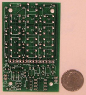
But we think a far cooler option is to build your own. It's a pretty simple project, especially if you know anything about electronics. We already have a design for a simple yet capable blue box called the Project MF Blue Box. You can download a complete schematic and printed-circuit board (PCB) layout, plus the software for programming an inexpensive PIC microcontroller to run it.
In fact, if you attended The Last HOPE Conference you might have received a PCB!
We are selling PCBs and pre-programmed microcontrollers for this project -- not to get rich, but just to simplify the task of making a blue box. Please send us mail for details.
Overview of the Project MF Blue Box
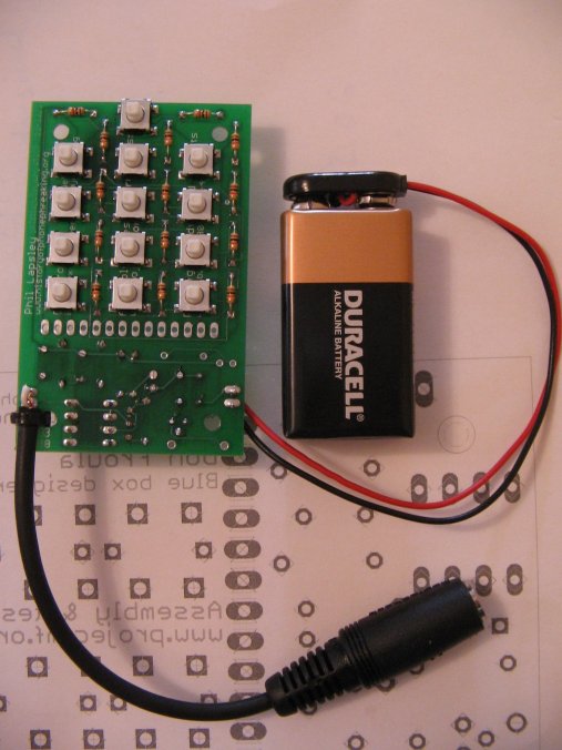
The Project MF Blue Box consists of:
- an 8-pin PIC 12F683 microcontroller
- a ceramic resonator
- 13 SPST switches for the digits 0 through 9, KP, ST, and 2600
- a handful of resistors and capacitors
- a diode or a 78L05 voltage regulator, depending on whether you want to run the box from a 6-volt or 9-volt battery
- an external speaker
The design goals were that it be small, low-power, easy to assemble, have minimum parts count, and not use any esoteric or hard-to-find parts, All the parts can be found at Radio Shack or Digikey and total materials cost is well under $20.
Schematic, PCB layout, and Bill of Materials (BOM)
The schematics, PCB, and bill of materials (parts list) are available in several formats:
- Schematic: PDF, Cadsoft Eagle
- PCB: Gerbers and drill file (zip), Cadsoft Eagle PCB layout
- Bill of materials: Microsoft XLS format
You can also download a convenient pdf of all of the above plus assembly instructions.
Eagle is a schematic design and PCB layout program from CadSoft that runs on Windows, Macintosh, and Linux computers. It is only necessary if you want to modify our schematic or PCB design. You can use the free ("trial") version, which can be downloaded from CadSoft's web site.
Making a PCB
If you'd like to make your own PCB you can download the Gerber zip file above and submit it to a PCB manufacturing house of your choice. One good option for hobbyists is Bare Bones PCB. We've also heard good things about SparkFun Electronics / BatchPCB though we haven't used them ourselves.
Programming the PIC
Your easiest route is to buy a pre-programmed PIC, which we're happy to sell to you at nominal cost. Contact us via email at bluebox@projectmf.org for details.
That said, you can also program it yourself. You will need to download a zip file of the blue box firmware: BBsoftware.zip. This is the software that runs on the PIC microcontroller and provides the blue box functionality. The .hex files are pre-compiled object code. The .pbc files are the PicBasic Pro sourcecode. Files with a "SP" suffix in their filenames are for a reverse keypad layout. (If you want to modify the source code you will need a copy of the PicBasic Pro compiler, which costs $250. If you just want to use our precompiled .hex files, you don't need to spend any money.)
You will need a PIC programmer. We like the free WinPic800 programming software and the (not-free) JDM Enhanced Programmer.
Assembly Instructions and Tips
We suggest you download a complete pdf copy of the most up-to-date assembly instructions and schematics. (The information below more or less replicates the contents of this file.)
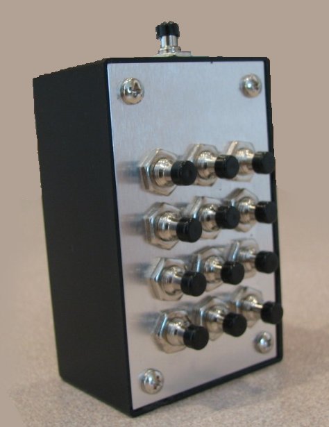
The circuit board is designed to fit in place of the front panel of a Radio Shack enclosure, part number 270-1801.
If the Radio Shack enclosure is used, the pushbutton switches may be mounted on the back side of the board. This is the solder side, opposite of where the other components are mounted. This allows the board to be mounted in the box with the components down and the buttons facing up. If this is done, the LED power indicator (LED1), if used, may also be mounted on the solder side as a power indicator.
If the buttons are mounted on the back side, the SP version of the PIC firmware must be programmed. This SP version reverses the switches left to right, but is otherwise functionally identical to the regular firmware. The web page has both versions available.
The 1 megohm resistor (R17) near the resonator is normally not required. Only use it if you experience erratic operation of the device.
The recommended speaker for use with the device is a 150 ohm earpiece from an old "500" type telephone handset. These are the standard handsets used by Western Electric, ITT and other phone manufacturers for decades. See the parts list for sources. Just unscrew the earpiece from an old phone, loosen the two screws, and remove the earpiece. BE SURE TO CLIP OUT THE VARISTOR (A SMALL COMPONENT SOLDERED BETWEEN THE SCREW CONTACTS) OR YOUR TONES WILL BE DISTORTED AND THE BOX WILL NOT WORK RELIABLY!
The box may work with other impedance speakers/earphone elements, with varying volume and hiss. Lower impedances will reduce the effectiveness of the PWM low-pass filter in the circuit, increasing hiss. Speakers vary widely in their efficiency (volume for a given power input), so you may need to experiment. The output power is low to keep the circuit simple.
The box may be connected to an external amplifier for volume control, or to a computer sound card input. If this is done, the output should be connected through a small .33 mf capacitor to block the DC component present when tones are being played.
The box draws 15-20 mA of current when generating tones. Battery life is very good if the unit is always switched off between uses.
If a 6 volt battery is used (a 4LR44/476A/L1325 designed for dog collars works well, as well as 2 CR2032 lithium coin cells wired in series), be sure to populate the diode (D1) on the board and omit the 78L05 (IC2), C1, and C2. The 4LR44 fits into an "N" battery holder, available at Radio Shack, if a small nut is used as a spacer on the negative side.
If a 9 volt rectangular battery is used, populate the 78L05 (IC2), C1, C2 and omit the diode (D1).
Note that you cannot install both D1 and IC2; install one or the other!
If the optional LED power indicator is installed (LED1 and R20), current consumption will increase by an additional 15 milliamps. This will reduce the battery life significantly. This is particularly important if using the 6 volt battery option, as the battery is of lower capacity. You can try a larger resistor for R20 (try 1000 ohms) to reduce LED brightness and current consumption.
Using the Project MF Blue Box
The Project MF Blue Box is a sophisticated little device! Here's a video tutorial from YouTube, plus more detailed information below.
Both MF and DTMF are supported. When initially programmed, the chip defaults to MF mode on powerup. The powerup mode is stored in FLASH memory. This may be temporarily toggled to the opposite mode by holding down the 2600 key while powering up. The next powerup reverts to the default tone mode. The default tone mode may be persistently toggled by holding down the "*" while powering up. This will toggle the tone mode, but also write the new setting to eeprom so subsequent powerups will default to the opposite tone mode. Two tones confirm the write to FLASH memory.
Two tone durations/spacings are supported, 75 ms. (default) and 120 ms. The tone duration/spacing is stored in FLASH memory. The duration/spacing may be permanently toggled by holding down the "#" key at power up. This will toggle the duration/spacing and write the new value to FLASH for subsequent powerups. A tone confirms the write to FLASH. The duration/spacing value is used in manual mode and also in memory playback mode. The KP tone is always 120 ms.duration, regardless of this setting. The 2600 tone duration is always 1.5 seconds.
There are two operating modes, normal and playback. The chip always powers up in normal mode. Operating modes are toggled by holding down the 2600 key for 1 second. Tones confirm the mode change. In normal mode, dialing is manual using the current tone mode and duration settings. In playback mode, each keypad key will play back any stored dialing sequences.
There are 12-32 digit dialing memories, one for each keypad key. On power-up, a playback to normal mode change, or a dialing memory write the chip stores the next 32 key presses in a RAM buffer. At any point, this buffer may be saved to one of the 12 dialing memories by pressing and holding the corresponding key for 2 seconds. (The digit played when initiating a write to the memory will not be saved.) A tone confirms the eeprom write. Memories are cleared by storing to memory immediately after a power-up, mode change from playback to normal, or after a previous dialing memory save. The MF/DTMF tone mode is saved in memory, so the dialing memories may contain a mix of MF and DTMF sequences. If a 2600 tone is saved, a 1.5 second fixed delay will be added after the tone to allow for a wink ack from the trunk. Then, any additional tones will play.
Short instructions:
Operating functions:
- Toggle beteen manual and playback modes: Hold 2600 button for two seconds
- Clear keypress memory buffer: power off then on (also cleared after previous store or mode change)
- Store keypress memory buffer: Hold down any keypad key for two seconds
Configuration functions:
- Temporarily switch between MF/DTMF modes: Hold down 2600 while powering up
- Permanently switch default power-up mode between MF/DTMF: Hold * while powering up
- Permanently toggle between short (75 ms.) and long (120 ms.) tone duration: Hold # while powering up
Long Instructions
On power up, a mode change, or a memory store operation, the device saves the tone mode plus the next 32 keypresses in a buffer. This buffer maybe written to one of the twelve non-volatile memory locations (1-12) by pressing and holding the corresponding digit for two seconds. The tone mode (MF or DTMF) is saved as well as the buffer. The tone played when the key is first pressed to store will not be recorded. Reset the digit buffer by cycling power, saving a buffer to FLASH, or changing normal/playback modes.
The box operates in two modes. In the default normal mode, it plays tones manually. Pressing and holding the 2600 button more than one second toggles to the playback mode. In this mode, sequences stored in the 12 memories may be played by pressing the corresponding key. Another two second press of the 2600 key, or power cycling, returns to normal mode.
The powerup tone mode may be temporarily toggled between MF and DTMF by holding the 2600 button down while powering up. The current tone mode is stored to the non-volatile memory slots as well as the buffered digits, so the memories may contain a mix of MF and DTMF sequences. Both MF and DTMF may not be saved in the same memory slot.
The power-up tone mode and tone duration/spacing are stored in FLASH and read at powerup. The power-up defaults may be changed. Holding down the "*" key at powerup will read the current tone mode (MF or DTMF) from FLASH, toggle it and write it back to FLASH. Similarly, holding down the "#" key while powering up will toggle the default tone duration spacing between 75 ms. and 120 ms. The KP tone duration is always 120 ms., regardless of this setting. The 2600 tone is always 1.5 seconds duration.
Memory locations may be cleared by pressing and holding the corresponding key in normal mode immediately after the buffer has been cleared at power-up, after a mode change back to normal mode, or after storing a digit sequence.